
building a $500 6-dof robot arm: the plan
A six-axis robot arm I design, print, wire and program myself for $500: requirements, architecture, Denavit–Hartenberg geometry and the budget. Part 1 of a series.
I want a robot arm on my desk. Not a toy servo arm that wobbles when you look at it, and not a $5,000 industrial one either: a real six-axis manipulator that I design, print, wire and program myself, for $500.
This is the first post in a series where I build exactly that, step by step, with the maths done in Python along the way. Every figure in this series is generated from code you can run yourself: github.com/hfmuzb/python-experiments.
the starting point #
I began with an industrial-style design spec for a 6-DOF arm: harmonic drives, brushless motors with field-oriented control, 18-bit encoders, EtherCAT, ROS 2 on a real-time PC. The maths in it (kinematics, dynamics, trajectory planning) is universal. The hardware is not: priced out, it lands well above $5,000.
So the plan is to keep the maths and rebuild the hardware around three constraints:
- $500 total, everything included
- 24 V power
- mostly 3D printed, with aluminium only where plastic would fail
the spec #
- degrees of freedom: 6 (base, shoulder, elbow + 3-axis wrist)
- payload: 100 g, plus a ~100 g gripper
- reach: about 0.40 m to the flange
- repeatability: ±1 mm
- joint speed: 60 °/s (arm), 90 °/s (wrist)
- supply: 24 V DC
- budget: $500
Small numbers on purpose. Every gram at the wrist has to be held up by the shoulder, through a lever arm of almost half a metre. Keeping the payload light is what makes cheap motors and printed gears viable at all.
how it fits together #
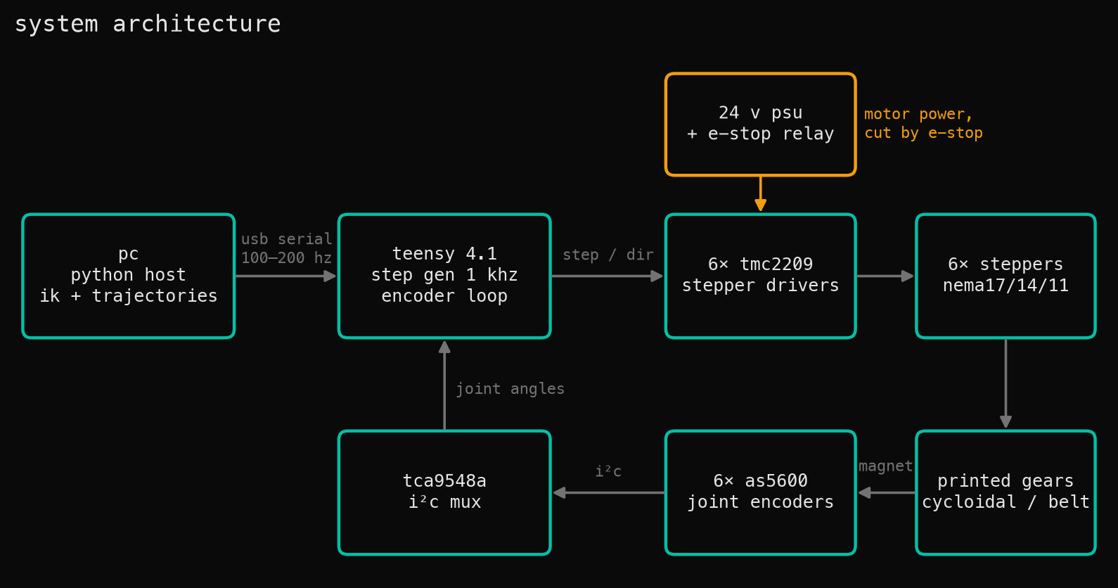
The architecture in one paragraph: a Python program on my PC solves the inverse kinematics and plans smooth trajectories, then streams joint targets over USB to a Teensy 4.1. The Teensy turns them into step pulses for six TMC2209 stepper drivers. Each stepper drives its joint through a 3D-printed reduction (cycloidal drives for the big joints, belts and small planetary gears for the wrist). A cheap AS5600 magnetic encoder on every joint output reports the real angle, so the controller can catch skipped steps and gear backlash.
The big trade-offs compared with the industrial spec:
- harmonic drives → printed cycloidal drives. A harmonic drive alone costs more than the whole budget.
- brushless + FOC → steppers. Steppers hold position open-loop and cost about $12 each.
- 18-bit encoders → 12-bit AS5600. Roughly 0.6 mm per count at full reach, inside our ±1 mm goal.
- brakes on the shoulder → counterbalance spring. It stops the arm dropping when power is off, and frees up torque.
- ROS 2 on real-time Linux → plain Python. The microcontroller does the real-time work, so the PC doesn't have to.
One design rule matters more than any of these: keep the motors close to the base. The elbow motor sits at the shoulder and drives the elbow through a belt. A motor at the elbow would weigh about 0.3 kg at the end of the upper arm, and the shoulder would have to lift it on every move.
the geometry: Denavit–Hartenberg parameters #
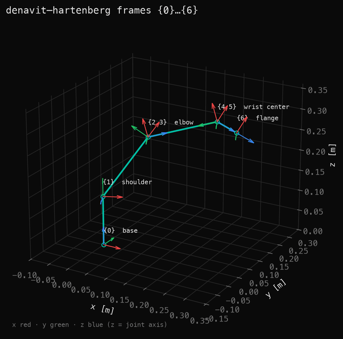
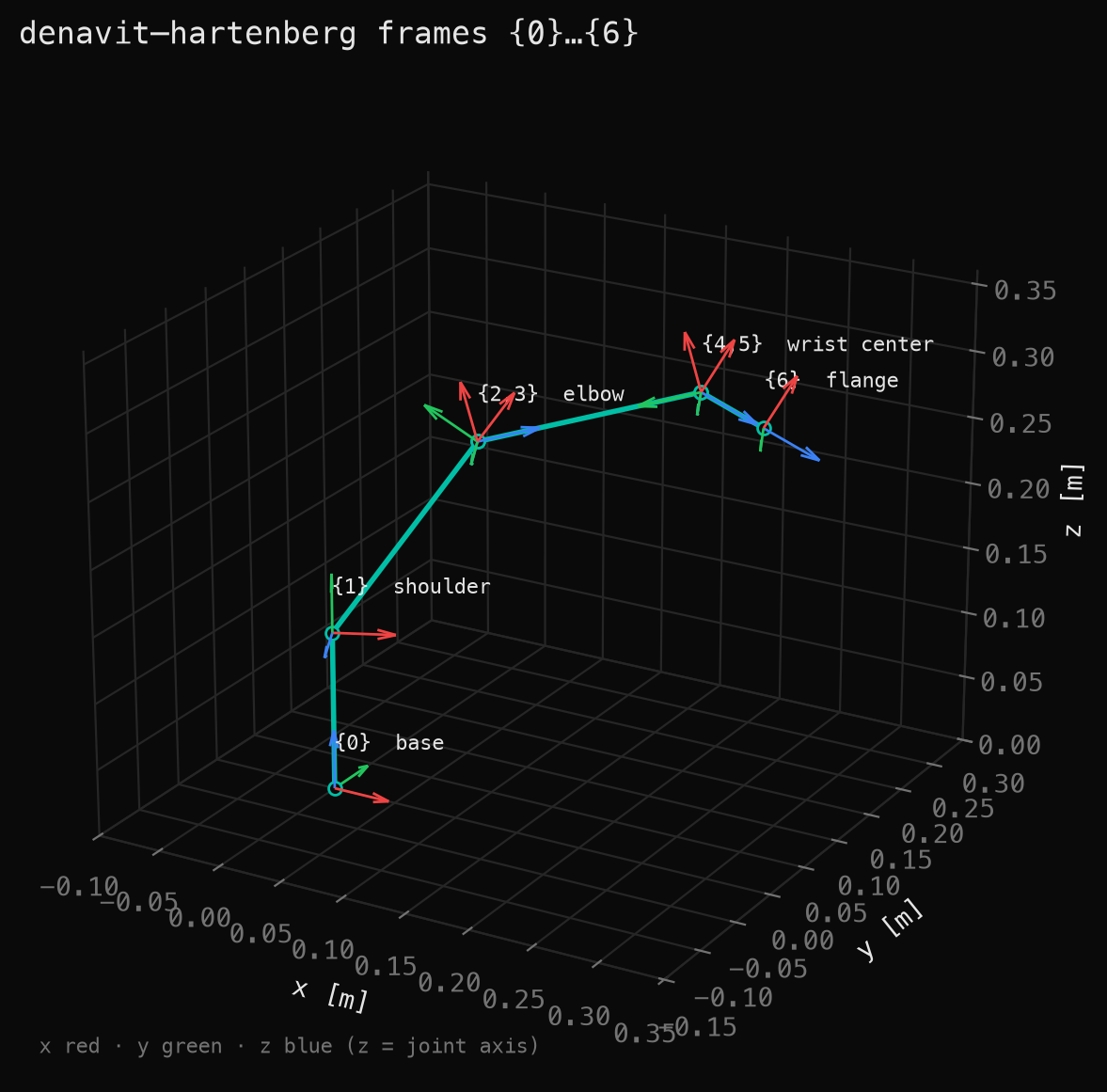
The arm has the classic "anthropomorphic arm + spherical wrist" layout: three joints position the wrist, and three wrist axes that meet at a single point orient the gripper. That intersection matters. It splits inverse kinematics into a position problem and an orientation problem, and both can be solved in closed form. That's the next post.
To describe the geometry, I use the standard Denavit–Hartenberg (DH) convention. Each joint gets a coordinate frame, and four numbers describe how to get from one frame to the next:
Here is the joint angle, the offset along the previous joint axis, the link length, and the twist between consecutive axes. For this arm:
The elbow joint has a offset, and the forearm length sits in rather than . That's standard for a spherical wrist, and it's an easy detail to get wrong.
In code, the transform and the chain of frames are only a few lines:
def dh_transform(theta, d, a, alpha):
    ct, st = np.cos(theta), np.sin(theta)
    ca, sa = np.cos(alpha), np.sin(alpha)
    return np.array([
        [ct, -st * ca,  st * sa, a * ct],
        [st,  ct * ca, -ct * sa, a * st],
        [0.0,      sa,       ca,      d],
        [0.0,     0.0,      0.0,    1.0],
    ])


def frames(q, links=ARM):
    T = np.eye(4)
    out = [T]
    for qi, link in zip(q, links, strict=True):
        T = T @ dh_transform(qi + link.offset, link.d, link.a, link.alpha)
        out.append(T)
    return out
Multiplying all six gives the pose of the flange relative to the base, . I checked this implementation against Robotics Toolbox for Python on 200 random poses, and the two agree to .
where the $500 goes #
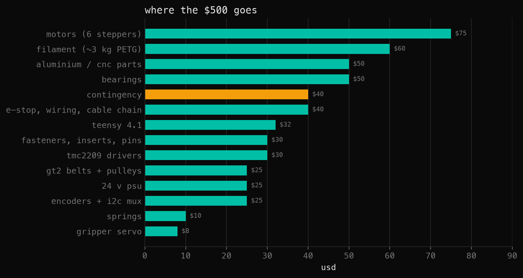
Motors are the single biggest line, but the less exciting items (filament, bearings, aluminium parts, fasteners) add up to more. The $40 contingency isn't optional. The first printed gearbox will not be the last one.
The aluminium is limited to three places where plastic genuinely fails: the shoulder output hub, which carries the biggest bending load; the eccentric shafts of the cycloidal drives, which need about 0.05 mm precision; and the base turntable plate, whose stiffness sets the accuracy of everything above it.
the roadmap #
The first articles need no hardware at all. Everything gets designed and checked in simulation while parts are on their way:
- this post: requirements, architecture, geometry
- kinematics: forward and inverse kinematics (all 8 solutions), the Jacobian, and singularities
- dynamics: how much torque each joint really needs, and how a spring can do half the work
- trajectory planning: smooth motion that steppers can follow without skipping
- drivetrain and parts: choosing motors and gear ratios, the final bill of materials
- printing a cycloidal gearbox: generating the gear profile in Python, then testing it
- electronics and safety
- firmware: steppers with an encoder loop on top
- host software: teach-and-replay and straight-line moves
- calibration
- validation: does it actually hit ±1 mm?
Next up: kinematics. Given a target position and orientation for the gripper, which joint angles get us there? It turns out there are up to eight answers.